Bench Power Supply

I saw a long time ago that someone built a bench power supply using a power supply from an old computer. This is why, when I found an old pre-Pentium computer (fully working with Win 95 on it) in the garbage, I implemented this idea.

Bench power supplies (PS) are very handy for testing electronics because they are reliable, stable and secure. It supplies variable voltage in a fairly large range, and detects when you are darning too much current from it or when its outputs are shorting, turning itself off elegantly instead of burning or overheating like some cheap power adaptors. Nevertheless, this kind of equipment cost around 200$ (usually more), which is very expensive (at least to me).

My version is much cheaper, I estimate it costs 8$ (4% of the retail cost). Of course, it has some limitations, but not that many.

Enough chitchat, let’s get started.

Materials:

  • 5 female surface-mount banana connectors (I had to buy them @ 8 for 12$)
  • A computer power supply (from the old computer I found)
  • 2 LEDs + surface mount (I got them from the same computer)
  • A switch (I had it lying around)
  • A resistor (use this calculator to get a value for your resistor)
  • 4 protective rubber pads (they give a feminine touch)
  • A power cord (Duh…)

Putting it together

Of course, my computer PS is not standard (GPC 145-4001), so I couldn’t find its specifications anywhere. So, I did a bit of reverse engineering (poking around) and figured out the pinout shown in this table:
Note: for P7 (P1, P2,… are the actual name written on the plugs) the yellow wire outputs 5V when the power supply is plugged in regardless of it being on or off. Also, when the violet wire is grounded, the power supply turns on. It goes off as soon as the violet wire is not grounded. Finally, the maximum power output is 150W, pretty respectable.

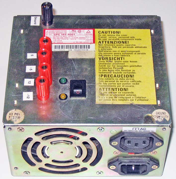
In order to control the power supply and show when it is on/off and plugged-in, I attached the following circuit to P7:


This works very simply: the yellow LED turns on when the PS is plugged to the mains and the green LED turns on when the switch is closed and the PS turns on.

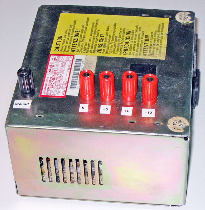
I desoldered all the wires (P1, P2 ad P6) from the PS, leaving just one for each output (5V, -5V, 12V, -12V, and GND). Desoldering them is better than cutting for obvious reasons (less clutter, more reliable, etc). The output wires will be attached to banana connectors mounted on the PS case in order to make them more accesible (make sure the connectors are isolated from the case).

In order to pack everything inside the PS case, I drilled 5 holes for the banana connectors, 2 smaller holes for the 2 LEDs, and drilled and filed a rectangular hole for the switch (I know, it would have been much simpler to use a round switch). Since everything fits very tightly in the case, the holes placement must be carefully planned so the added parts won’t interfere with the PS (i.e. stop the fan, make undesired connections between the components).

The last step is to put everything together and close the case.

The newly born power supply will turn off nicely when you short its outputs or when the load exceeds its maximum power output capacity (i.e. when you plug a big motor or a power tool to it). By combining the outputs (DC) you can get 5V (GND to 5V), 7V (5V to 12V), 10V (-5V to 5V), 12V (GND to 12V), 17V (-5V to 12V), and 24V (-12V to 12V).

As a finishing touch I added rubber pads on the bottom so it doesn’t scratch my desk and I labeled the outputs using a labeling machine (pretty fancy).

Future improvements
I will add a variable voltage divider in order to easily get other useful voltages out of it, such as 3.3V and 9V.

Some Ideas

This is a list of the things I would like to build (any ideas are welcome):

  • Chocolate Printer: a printer that uses chocolate instead of ink and is capable of printing 3D objects (I’ve seen some guy stolen my idead, but thats OK, I don’t mind).
  • Vibrating Pen: a pen that vibrates producing funny writing (for children).
  • Electric Bike: a bike that uses an electric motor for propulsion.
  • Frictionless Electricity Generation on a Bike
  • Skype Phone Ringer
  • Faraday’s Torch: the ones you shake.
  • Big Van de Graaff Generator
  • OWI 007 Computer interface
  • Weather Cube: a transparent cube that emulates current or future weather on its inside (uses internet weather information).
  • Wooden IPod Case (nano)
  • Foldable Bike Trailer
  • Lock Picks
  • Binary Clock

La Cucaracha

——-[!]——-

Update: La Cucaracha has got lots of attention lately (mainly thanks to Alan Parekh from HackedGadgets). I found some of its cousins built by 7 year olds. See them at ArtBots Robots.

——————

This is a small and very simple robot that requires no electronics. It is inspired on La Coccinelle. They both work according to the same principle, but their bodies and wheels are different. Also mine uses rechargeable batteries so I don’t need to buy new ones after just a few hours of usage.

Materials:

  • 2 big plastic bottle caps (much like the PC Thermometer)
  • 2 Wire ties
  • 1 screw
  • 2 DC Motors
  • 2 toy wheels
  • 1 switch (a small one so it fits on the bottle cap)
  • Some cables
  • 1 Cable holder
  • 1 Rechargeable battery pack w/ charger
  • 1 3.5 mm audio jack (male and female)
  • 2 paper clips (regular size)
  • 2 SPDT Switches (commonly found in printers)

Main Idea

The idea is to construct a robot that can move around and that will backup and change the direction of the motion when it hits an obstacle.

Putting it together

  1. Cut two diametrically opposite holes on the side of the caps so the motors fit in there. Chose one of the caps as your base cap (the one thats goes on bottom).
  2. Pierce two small holes on the top of the base cap in order to tie the motors to the cap using the small cable ties.
  3. Cut two more holes spaced by about 1.5 cm so the switches fit in tightly (seeing the pictures help visualizing this).
  4. Drill a hole in the center of both caps with the same diameter as your screw.
  5. Install the switch and the female audio jack on the top bottle cap.
  6. Connect everything together as shown in the circuit diagram. I used the audio jack to make the charger connection. The charger is simply a 3V power adapter connected in series with a diode in the + terminal.
  7. Solder the paper clips to the SPDT blades and add a little solder blob on each paper clip end so they look more like antennas.
  8. Test to see if the circuit works properly. When the robot is switched on, both spindles should spin so it goes forward. If an antenna is pushed, the spindle on the opposite side (left spindle if right antenna) should spin backwards.
  9. Fasten the motors to the base cap using the cable ties and secure the other cap on top of it using the screw. Also secure the cable holder using the same screw on top of the top cap, this serves as a battery holder.
  10. Insert the toy wheels on each motor spindle. You can also add a piece of plastic for stability under the base cap.

It’s done! Now you have a small robot that will go around your house bumping on whatever is on its path.

Coming Soon

Some projects I will be writing on soon:

  • La Cucaracha, a robot without electronics
  • Cheap Bench Power Supply, see this picture
  • Laptop USB Lamp
  • CD Lamp², the obvious evolution of the CD lamp
  • Cornstarch Pet, a small project based on this experiment
  • Ultra Cheap XBOX USB adaptor.
  • Skype phone ringer.

Make Your Girlfriend Happy For 0.25$

I saw in this site (try this one if the link is broken) that we can build a coin ring using a spoon, a drill, a Dremel and some metal polish. Immediately, I wanted to do one.

Materials:

  • An ordinary 0.25$ coin (Canadian in my case)
  • Lots of patience

Canadian Quarter

Making it happen

Warning: your family and specially your dog could become agitated if you hit a coin with a spoon during an entire day.

I started by hitting my coin on its edge with a spoon. I used a small metal plate a found laying on the street as a rigid surface for the hitting. After about 2 hour of lots of hitting and almost no change I tried using a small hammer. It bended the coin faster but the results were a little deceiving. In the original site pictures, you see the inside of the coin bending uniformly outward., Instead I got flat edge and a smashed inside. After about two more hours of hitting I switch to a normal full-sized hammer.

I hit the coin until I got it to the right diameter (my estimation of my girlfriend’s finger diameter) and then I hit it with the spoon once again. The spoon flattens the edge surface making it smoother (which means less sanding and polishing afterwards). Also the spoon allows for fine control over the shape of the ring.

Once I got the edge to the right shape and diameter, I drilled a hole on the coin. I then used a screw to secure the coin to a drill and polished the outside of the rim by making it spin very fast. I used a fine sandpaper at first and some Brasso and a cloth afterwards.

Removing the inside of the coin was the most difficult part since I don’t have any clamp that can hold it without damaging it. Also, I could not preserve the outer part of the coin’s inside as shown in the original site since mine was completely smashed. Anyways, in the end I removed the body of the coin usind some files and polished the inside of the newly born ring.

I gave the shiny (except for some dark spots caused by my inaccurate hitting) ring to my girlfriend who was very happy with it. I was happy to see it fitted her finger (although it was a bit loose).

Later, I discovered that the guy in the site used a silver coin (i know it is an obvious fact), which I suppose is easier to bend than my 94% steel coin.

Anyway, the end result is quite pleasing and nobody will believe you built a ring from a coin by hitting it with a spoon (unless you explain them how to proceed and show them pictures, people are very skeptical).

And yes I know, it is illegal to break money. This is why this never happened , you simply imagined visiting this site and seeing this project.

Return top

Welcome!

Here you will find my DIY projects, Robotic hacks, Nao 1337 videos, and more! Have questions about a project? Leave a comment!
Buy Levitra (vardenafil)60 mg Generic CialisBest Generic price Cialis60 mg Viagra OnlineBuy Cialis California Online