My computer finally died. After close to ten years of faithful service, my computer catastrophically failed one last time (this doesn’t necessarily mean I won’t try to fix it). Anyways, this pushed me to finally buy another computer after many years of searching around.
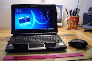
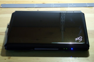
I chose to buy an Asus Eee PC 1000; I could not be happier with my buy.
The obligatory Eee PC specs:
- 1.6 GH Intel Atom CPU
- 1 GB RAM
- 40 GB SDD (8 + 32)
- 10 in LCD
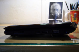
- SDD card reader
- Multi-touch touchpad
- Shiny black body
- WiFi draft n
The solid storage is great. It gives the peace of mind that I require to be able to take the laptop everywhere on my bike or in my backpack (I jump around a lot). I have currently formatted both disks with ext3 partitions mounted with the realtime option. I know about the life expectancy concerns but I have not found any reference that says that my SDD drives will die prematurely if I use the ext3 filesystem instead of ext2. Also, the ext3 filesystem is more robust and it doesn’t corrupt files if it is not checked often or if the computer is turned off abruptly.
I installed Kubuntu by creating a live USB stick using UNetbootin and then setting the USB stick as the primary device in the BIOS. The Eee PC then boots with the USB key and Kubuntu can be installed normally. For more info about installing Ubuntu please refer to this page.
In order to have the WiFi adapter and the wired Network card working, I used the kernel packages from Array.org.
The battery life is awesome. It is much longer than in conventional laptops, even with the processor working at full speed, the LCD at full brightness and the WiFi adapter enabled. Also, the keyboard is very nice and not too small. It is really easy to get used to it. For more info about the Eee PC performance, please watch the following video:
The touchpad is very good and the multitouch feature works very well. It is hard to go back to normal touchpads. Nevertheless, a mouse is much faster and precise, so I decided to buy a mouse: the Logitech VX Nano.
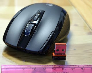 Needless to say, the VX Nano is wonderful and a perfect match for the Eee PC. They have both been carefully designed with particular attention to detail and quality. They come with carrying cases and are very sturdy and good looking.
It is obvious that I’m happy with my two new toys.
Finally, KDE 4.1 is simply perfect. It is beautiful, fast, and very well thought. In short: the perfect software for the perfect hardware.